With four different models to choose from, the Biltwell range of foot pegs for Harley-Davidsons is robust. Each model is designed and manufactured to complement different styles of custom motorcycles—everything from choppers and bobbers to street trackers, scramblers and bone-stock cruisers.
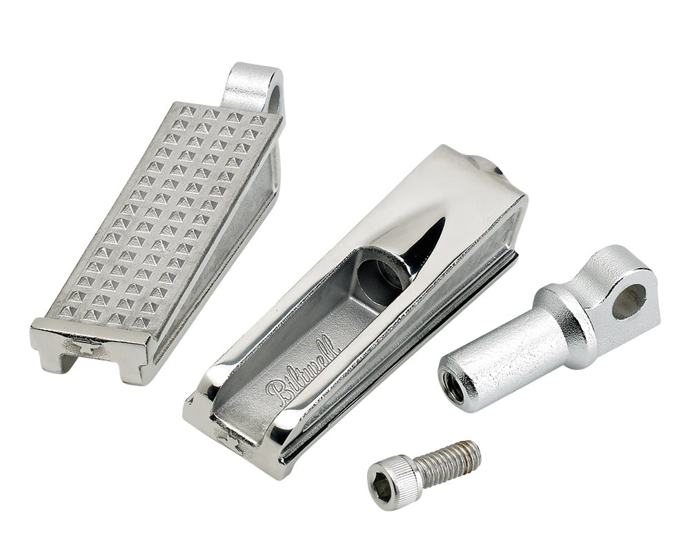
The Sanderson peg is our homage to the classic Anderson pegs prevalent on choppers in the ‘70s. The peg is investment-cast stainless steel, and its adjustable clevis is chromoly. Finishes include raw polished stainless steel and black electroplate. One 5/16-18 t.p.i. stainless steel Allen cap screw on each peg secures it to a clevis. This clever design allows you to adjust the angle of the foot peg infinitely through 360 degrees of rotation along its horizontal plane.
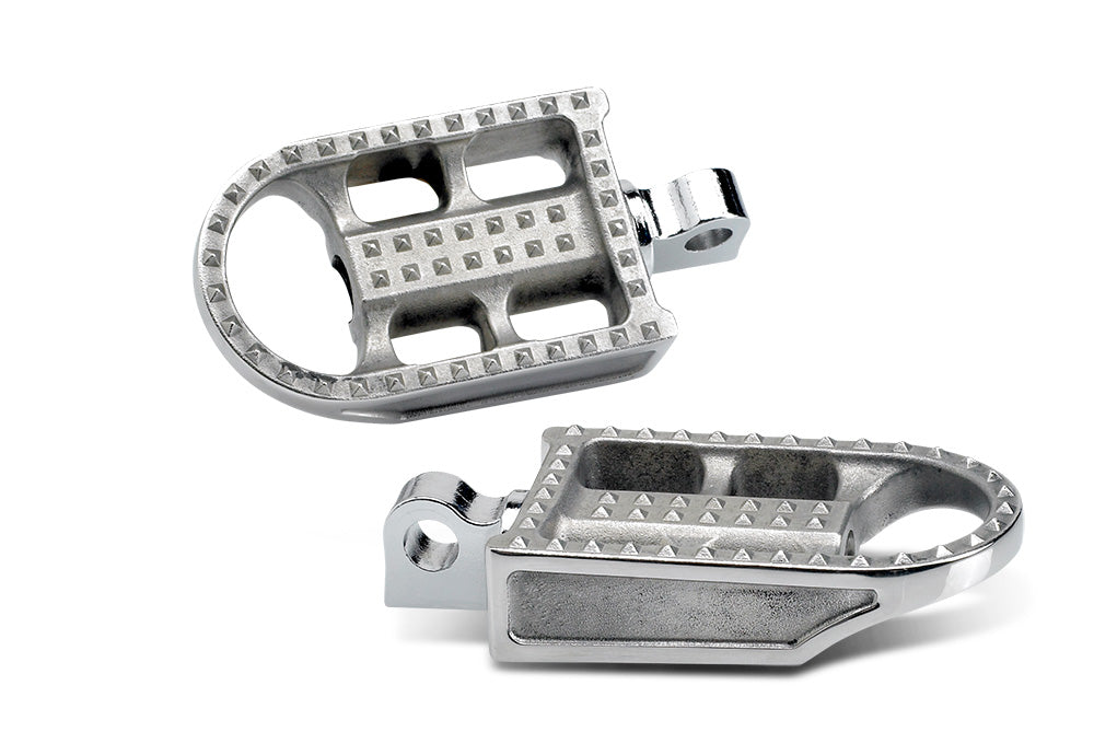
The Biltwell Mushman peg boasts the same construction, surface finishing and clevis technology as our Sanderson peg, but features a gently studded traction surface similar to modern motocross pegs. The Mushman looks most at home on dirt trackers, street trackers and café racers.
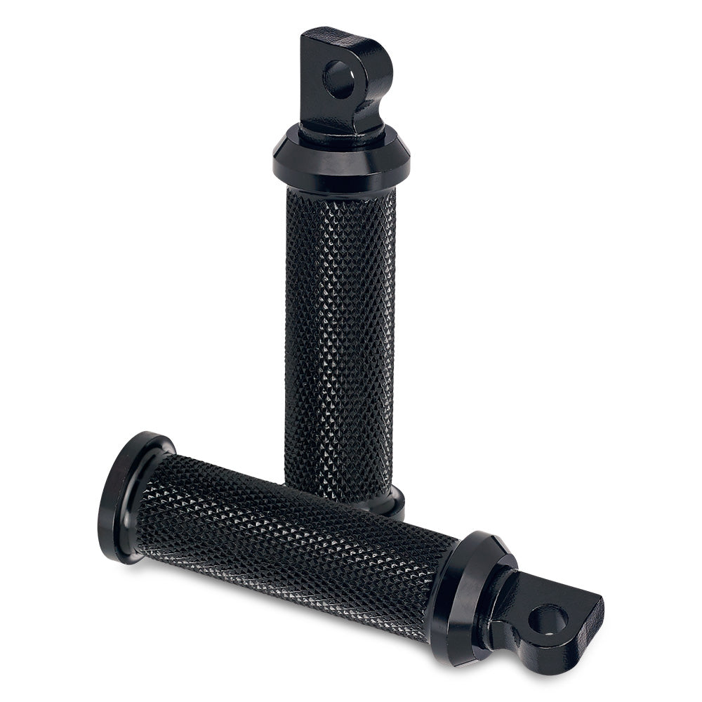
CNC’ed 6061 T6 aluminum construction, deep knurling and healthy proportions make our Rocker peg the choice for big riders on a budget. Like every Biltwell peg, the Rocker features our chromoly clevis and stainless steel mounting hardware for toughness and reliability.
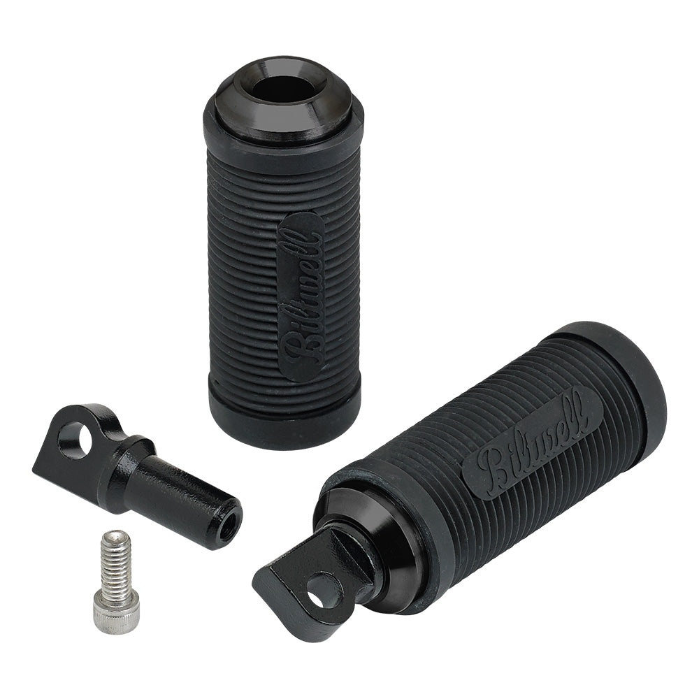
Our newest foot peg is the Norman. Fans of old-school British bikes will recognize the style. Our modern interpretation features a highly abrasion-resistant molded PVC peg on a CNC’ed aluminum core that bolts to our adjustable clevis like all Biltwell pegs.
Now that you know a little more about our pegs, it’s time to get your hands dirty with a simple install. Before you begin, disassemble both Biltwell pegs by loosening the 5/16-18 Allen cap screw inside each peg and remove the clevis from the peg body.
Step 1: Remove the old foot pegs from your motorcycle, being careful not to lose the wave washer/spring device between the peg clevis and fork on certain model-year Harley-Davidson foot controls. If you’re planning to re-use the stock pivot pins when you install your new pegs, DO NOT re-use the split cotter pins—throw them away and replace them with new ones. Better yet, consider replacing the pivot pins and associated hardware entirely with 3/8-16 t.p.i. stainless-steel Allen cap screws or button head Allen bolts with washers and nyloc nuts.
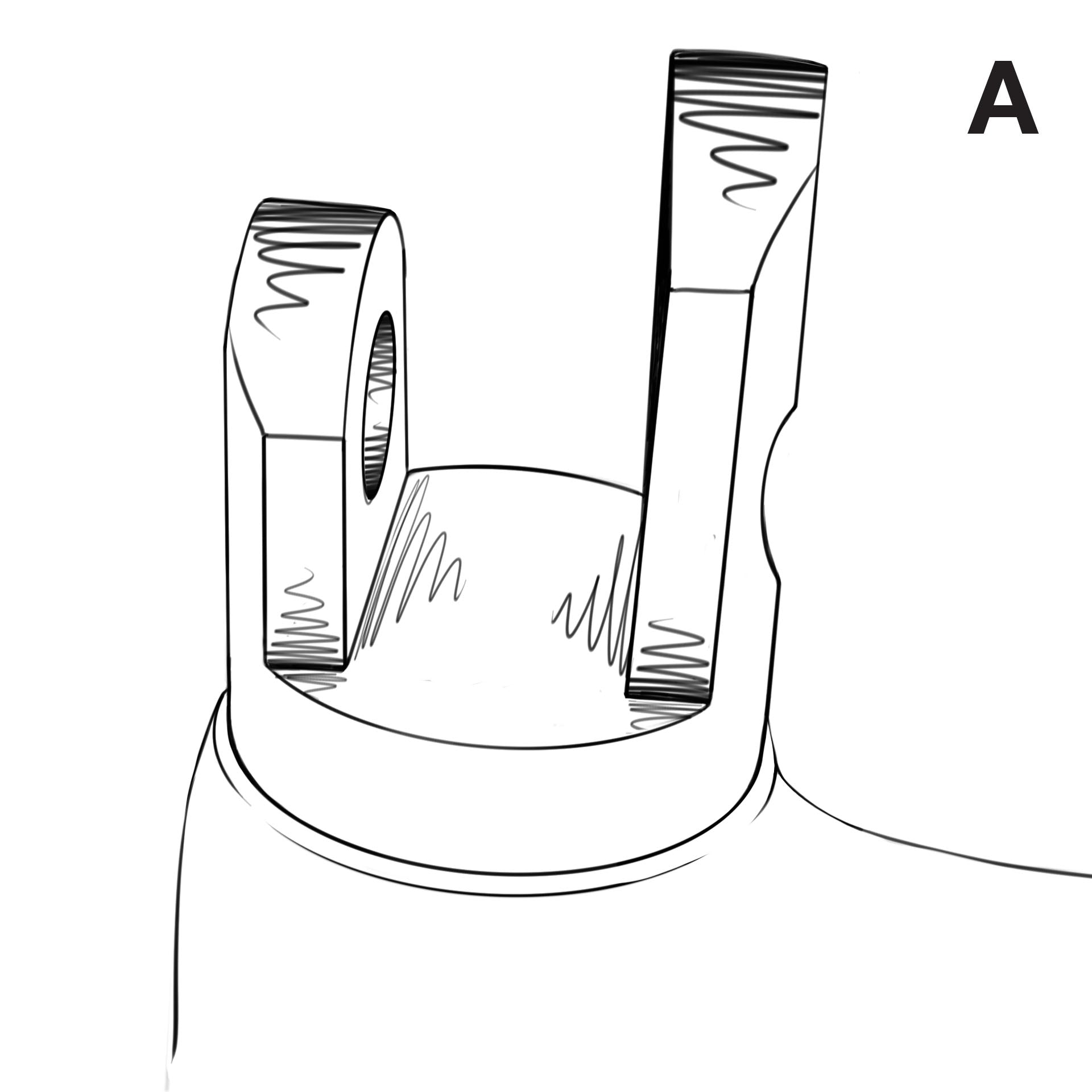
NOTE: A couple years ago Harley-Davidson introduced an asymmetrical clevis on certain model-year forward controls. It’s easily identified by the longer tab on one side (illustration A.) If your stock H-D features this clevis, follow steps 2 through 4. If the mounting forks on your foot controls are the standard equal-length design, proceed to step 5.
 Step 2:
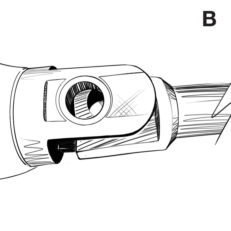
 The too-long clevis fork prohibits the male clevis from sliding all the way into H-D's stock clevis fork (illustration B.) Check your setup by inserting the new peg into the foot control clevis. If the holes line up, you’re in business. If the clevis fork prohibits your new peg from seating completely into the mount, proceed to step 3.
 Step 3:
 Carefully mark the longer of the clevis forks with a Sharpie. Keep your mark on the same plane as the opposite fork so the new peg will fold correctly.
Step 4: Using a hacksaw or a cutting disk on a 4-inch die grinder, carefully shorten the clevis fork you just marked so that it is the same length as the opposite fork. After cutting the fork to the appropriate length, carefully radius the top edge of the shortened clevis fork with a hand file or a flap disk on a 4-inch die grinder so the male clevis on your Biltwell foot peg can fold upward as designed. Execute this grinding and shaping in small increments so you don't remove too much material from the original part. Double-check your work during this step by inserting the hinge pin through the clevis fork and into the Biltwell male clevis, then fold the clevis upward. When the foot peg folds upward correctly without binding, the shortened mounting fork is complete.
Step 5: Hold one wave spring against the male clevis on your Biltwell foot peg and insert the assembly into the open fork on your foot control mount. If you are re-using the pivot pin, put a light coating of grease on its surface and insert it into the hole on the mounting fork and through the peg clevis/wave spring assembly. Put the washer onto the end of the pivot pin and insert a new cotter pin into the hole on the pin. Bend the cotter pin open to secure the assembly. Repeat Step 5 for the other clevis.
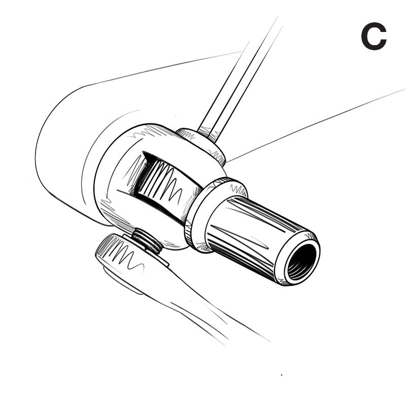
Step 6: If you are using nuts and bolts to secure your pegs, put a few drops of blue Loc-Tite onto the threads of a 2” long x 3/8-16 bolt and insert it into the fork on your foot control mount and through the Biltwell peg clevis/wave spring assembly. Use an Allen wrench and box-end wrench to tighten the mounting hardware to secure the clevis (see illustration C.) Repeat step 6 for the other clevis .
 Step 7:
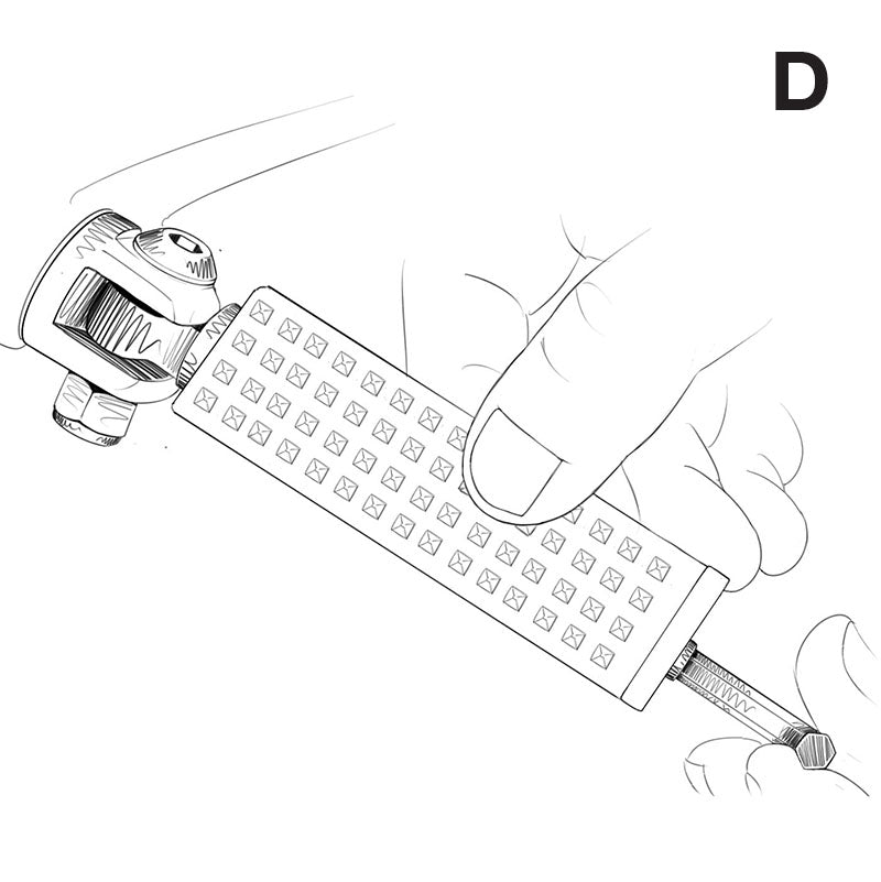
 Put a light coat of grease on the outer surface of the peg clevis. Insert the foot peg onto the clevis. Put a drop of blue Loc-Tite on the 5/16-18 Allen cap screw and thread it into the end of foot peg. Hold the peg at the desired angle and torque the 5/16-18 bolt to 12-18 ft. lbs. (illustration D.) Repeat Step 7 for the opposite peg.
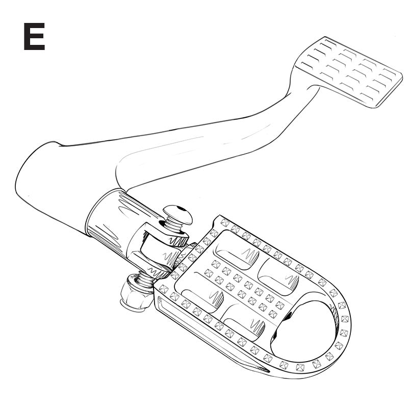
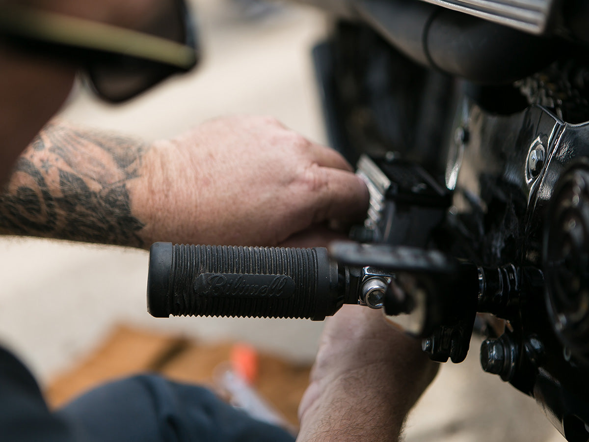
Biltwell Mushman foot peg installed on the brake/right side of a late-model Sportster with a 3/8-16 Allen cap bolt and nyloc nut.
Before you ride: If you used stock pivot pins to install your new Biltwell foot pegs, double-check the cotter pins—are they bent open correctly to ensure the pins remain tight? If you used bolts and nyloc nuts, make sure the threads pass all the way through to each nut to fully engage the locking function. Check the torque specs on the 5/16-18 Allen cap screws that hold the foot peg onto the adjustable clevis—12-18 ft. lbs. If everything is correct, fire up your scooter and give your new pegs a 10-mile shakedown. Come home and triple-check everything before hammering out the big miles
[embedyt] http://www.youtube.com/watch?v=lhRPlIImyA0[/embedyt]

[embedyt] http://www.youtube.com/watch?v=Rk5dIJ6boFE[/embedyt]

[embedyt] http://www.youtube.com/watch?v=W3CqQp4_csw[/embedyt]

[embedyt] http://www.youtube.com/watch?v=Q7U7GhO4lN0[/embedyt]
 With four different models to choose from, the Biltwell range of foot pegs for Harley-Davidsons is robust. Each model is designed and manufactured to complement different styles of custom motorcycles—everything from choppers and bobbers to street trackers, scramblers and bone-stock cruisers.
 The Sanderson peg is our homage to the classic Anderson pegs prevalent on choppers in the ‘70s. The peg is investment-cast stainless steel, and its adjustable clevis is chromoly. Finishes include raw polished stainless steel and black electroplate. One 5/16-18 t.p.i. stainless steel Allen cap screw on each peg secures it to a clevis. This clever design allows you to adjust the angle of the foot peg infinitely through 360 degrees of rotation along its horizontal plane.
 The Biltwell Mushman peg boasts the same construction, surface finishing and clevis technology as our Sanderson peg, but features a gently studded traction surface similar to modern motocross pegs. The Mushman looks most at home on dirt trackers, street trackers and café racers.
 CNC’ed 6061 T6 aluminum construction, deep knurling and healthy proportions make our Rocker peg the choice for big riders on a budget. Like every Biltwell peg, the Rocker features our chromoly clevis and stainless steel mounting hardware for toughness and reliability.
 Our newest foot peg is the Norman. Fans of old-school British bikes will recognize the style. Our modern interpretation features a highly abrasion-resistant molded PVC peg on a CNC’ed aluminum core that bolts to our adjustable clevis like all Biltwell pegs.
 Step 2: The too-long clevis fork prohibits the male clevis from sliding all the way into H-D's stock clevis fork (illustration B.) Check your setup by inserting the new peg into the foot control clevis. If the holes line up, you’re in business. If the clevis fork prohibits your new peg from seating completely into the mount, proceed to step 3.
 Step 3: Carefully mark the longer of the clevis forks with a Sharpie. Keep your mark on the same plane as the opposite fork so the new peg will fold correctly.
Step 4: Using a hacksaw or a cutting disk on a 4-inch die grinder, carefully shorten the clevis fork you just marked so that it is the same length as the opposite fork. After cutting the fork to the appropriate length, carefully radius the top edge of the shortened clevis fork with a hand file or a flap disk on a 4-inch die grinder so the male clevis on your Biltwell foot peg can fold upward as designed. Execute this grinding and shaping in small increments so you don't remove too much material from the original part. Double-check your work during this step by inserting the hinge pin through the clevis fork and into the Biltwell male clevis, then fold the clevis upward. When the foot peg folds upward correctly without binding, the shortened mounting fork is complete.
Step 5: Hold one wave spring against the male clevis on your Biltwell foot peg and insert the assembly into the open fork on your foot control mount. If you are re-using the pivot pin, put a light coating of grease on its surface and insert it into the hole on the mounting fork and through the peg clevis/wave spring assembly. Put the washer onto the end of the pivot pin and insert a new cotter pin into the hole on the pin. Bend the cotter pin open to secure the assembly. Repeat Step 5 for the other clevis.
Step 6: If you are using nuts and bolts to secure your pegs, put a few drops of blue Loc-Tite onto the threads of a 2” long x 3/8-16 bolt and insert it into the fork on your foot control mount and through the Biltwell peg clevis/wave spring assembly. Use an Allen wrench and box-end wrench to tighten the mounting hardware to secure the clevis (see illustration C.) Repeat step 6 for the other clevis .
 Step 7: Put a light coat of grease on the outer surface of the peg clevis. Insert the foot peg onto the clevis. Put a drop of blue Loc-Tite on the 5/16-18 Allen cap screw and thread it into the end of foot peg. Hold the peg at the desired angle and torque the 5/16-18 bolt to 12-18 ft. lbs. (illustration D.) Repeat Step 7 for the opposite peg.

 Biltwell Mushman foot peg installed on the brake/right side of a late-model Sportster with a 3/8-16 Allen cap bolt and nyloc nut.
 Shop All Helmets
 Shop All Optics
 Shop All Accessories
 Shop All Gloves
 Shop All Luggage
 Shop All Apparel
 Shop All Etc.
 Outlet
 WTF Blog


